

Your Enclosure should now look similar to the image as shown below. Now replace the top cover as described earlier in this document, using 2 of the M3 screws, start them in the mounting holes on the right side of the Enclosure, be sure the wires are routed out of the exit hole.

Your controller should now look similar to the image shown below.īelow is an image with the bend in the Heat Shrink showing how your installation should look when your probes properly installed. Go ahead and place the probe connection on this 3 pin connector on you controller.
#CNC TOUCH PLATE WIRING INSTALL#
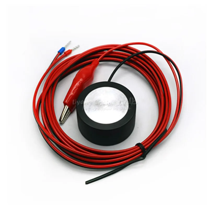
The location to install the probe is shown in the image below. There is a 3 pin connector on the current controller for the probe on, its on the opposite side from the USB and pores connections just below the row where the limit switches are plugged in and is oriented vertically. *Standard Shapeoko users be aware your controller will be 180 degrees (upside down) from the image below and will not have a Drag Chain. With the Top Cover removed your Controller will be similar to the image shown below. Remove the Top Cover as describe earlier in the document and put it in a safe place. This is shown in the image below and we will reference it again after the BitZero is installed. Note the Flange Screw will be used for the Ground to the alligator clip. To install the BitZero remove all the M3 screws holding the top cover on and set them aside in a safe place. If your 2.4d/e board is missing the RESERVED header, connect the BitZero using the adapter cable and follow the directions for connecting version 2.3 #Connect the BitZero to the RESERVED header as in the below pictures. You can now connect the probe to the 3-pin male header on the adapter cable.īeginning with version 2.4d, the boards have with a purpose-built connector that we can use for the probe, labeled “RESERVED”. Once both wires are plugged in, your board should look like this.


 0 kommentar(er)
